EdgeSwitch - VLANs 과 VLAN 인지 DHCP 서버
download at 2017-08-04T22:10:01Z origin
Overview
이 문서는 DHCP 서버를 설정하는 방법과 EdgeSwitch (ES)의 다중 스코프를 생성하는 방법에 대하여 서술합니다. 각 DHCP 스코프는 특정 VLAN에 라우팅 가능한 VLAN 인터페이스인 스위치 가상 인터페이스 (SVI) 를 통해서 할당합니다.
 Notes & Requirements: 1.7.1 버전 이상의 펌웨어가 설치된 모든 EdgeSwitch에서 동작합니다. 커맨드라인 인터페이스에 대한 기본지식과 기본 네트워킹에 대한 지식이 요구됩니다. 관련 문서 섹션을 참조하십시오.
이 문서에서 사용한 장비:
- EdgeSwitch-8-150W (ES-8-150W)
- 테스트 클라이언트 (Host, Phone, Server)
Table of Contents
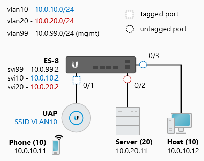
네트워크 다이어그램
네트워크 토폴로지는 아래와 같습니다. EdgeSwitch (ES)에서 사용한 인터페이스는 아래와 같습니다.
ES-8
- 0/1 (tagged) - VLAN10
- 0/1 (untagged) - VLAN99
- 0/2 (untagged) - VLAN20
- 0/3 (untagged) - VLAN10
UAP는 VLAN10 무선 네트워크에 태깅합니다. UAP 관리 트래픽은 태깅되지 않은 0/1 포트로 연결합니다. 해당 트래픽은 VLAN99 (native VLAN)에 위치합니다. 호스트와 서버는 VLAN10, VLAN20에 위치합니다. 각 클라이언트는 DHCP 주소를 ER로부터 부여받고 모든 트래픽은 Switch에서 ER로 흐릅니다.
Steps - VLANs 과 VLAN 인터페이스
이 문서는 ES가 기본 설정으로 구동하며 SSH 관리 접근이 가능하다고 가정합니다. 처음은 VLAN을 생성하고 특정 포트에 할당하는 작업입니다.
 CLI STEPS: 커맨드라인 인터페이스에 접속합니다. PuTTY와 같은 프로그램을 사용하여 SSH, 텔넷 등으로 접속할 수 있습니다.
- 특권 모드로 진입합니다.
enable
- VLAN과 VLAN 인터페이스 (SVI)를 생성합니다.
vlan database
 vlan 10,20,99
 vlan routing 10 1
 vlan routing 20 2
 vlan routing 99 3
 exit

Note
*vlan routing*<vlan-id> <interface-id (1-15)>포맷을 사용합니다. interface-id 는 VLAN 넘버와 일치하지 않아도 됩니다. 해당 아이디는 VLAN 인터페이스와 분리되어 사용합니다.
3. 환경설정 모드로 진입합니다.
configure
- 위에서 생성한 VLAN에 포트를 할당합니다.
아래의 환경설정은 0/2 포트를 VLAN20 (pvid)에 언태깅하고 0/3 을 VLAN10에 언태깅합니다. 0/1 포트는 VLAN10 (tagging)에 태깅되어 할당하며, VLAN99는 native VLAN으로 사용합니다. (pvid) 이후에는 필요 없는 VLAN을 포트에서 제거합니다.
interface 0/1
 description UAP
 vlan tagging 10
 vlan pvid 99
 vlan participation exclude 1,20
 vlan participation include 10,99
 exit

interface 0/2
 description Server
 vlan pvid 20
 vlan participation exclude 1,10,99
 vlan participation include 20
 exit

interface 0/3
 description Host
 vlan pvid 10
 vlan participation exclude 1,20,99
 vlan participation include 10
 exit
- SVI에 라우팅이 가능하도록 IP 주소를 할당합니다.
interface vlan 10
 ip address 10.0.10.2 255.255.255.0
 routing
 exit

interface vlan 20
 ip address 10.0.20.2 255.255.255.0
 routing
 exit

interface vlan 99
 ip address 10.0.99.2 255.255.255.0
 routing
 exit
- 라우팅 기능을 활성화합니다.
ip routing
 (ALTERNATIVE) GUI STEPS: 스위치 웹 관리 포탈(GUI)에 접속합니다.
- VLAN을 생성합니다.
Basic > VLAN > VLAN Wizard > Add VLAN
Enter 10,20,99 and select 'Add'
- 위자드를 사용하여 VLAN에 포트를 할당합니다.
Port 0/1: Excluded (E) for VLAN1 / VLAN20
Port 0/1: Untagged (U) for VLAN99
Port 0/1: Tagged (T) for VLAN10

Port 0/2: Excluded (E) for VLAN1 / VLAN10 / VLAN99
Port 0/2: Untagged (U) for VLAN20

Port 0/3: Excluded (E) for VLAN1 / VLAN20 / VLAN99
Port 0/3: Untagged (U) for VLAN10
- SVI를 생성하고 IP 라우팅 기능을 활성화합니다.
Routing > IP > Interface Configuration
Type: VLAN
VLAN: VLAN 10
Routing Mode: Enable
Admin Mode: Enable
IP Address Configuration Method: Manual
IP Address: 10.0.10.2
Subnet Mask: 255.255.255.0

Type: VLAN
VLAN: VLAN 20
Routing Mode: Enable
Admin Mode: Enable
IP Address Configuration Method: Manual
IP Address: 10.0.20.2
Subnet Mask: 255.255.255.0

Type: VLAN
VLAN: VLAN 99
Routing Mode: Enable
Admin Mode: Enable
IP Address Configuration Method: Manual
IP Address: 10.0.99.2
Subnet Mask: 255.255.255.0
- 라우팅 기능을활성하고, 기본 경로를 ER로 생성합니다.
Routing > IP > Configuration
Routing Mode: Enabled
Steps - DHCP 스코프
DHCP 임대 할당의 기본적인 룰 중의 한가지는 같은 네트워크 대역 (서브넷)에 인터페이스가 존재한다는 점입니다. 이 문서에서는 SVI를 인터페이스를 생성하였습니다. DCHP 스코프는 VLAN10, VLAN20, VLAN99로 연결합니다. 이 인터페이스들이 존재하기 떄문이며, 스위치는 어디서 주소가 할당되었는지 알 지 못합니다.
CLI STEPS: 커맨드라인 인터페이스에 접속합니다. PuTTY와 같은 프로그램을 사용하여 SSH, 텔넷 등으로 접속할 수 있습니다.
1. (선택사항) DHCP 서비스를 활성화합니다.
service dhcp
- DHCP 서버에서 할당하지 않는 IP 주소를 제외합니다.
ip dhcp excluded-address 10.0.10.0 10.0.10.10
ip dhcp excluded-address 10.0.20.0 10.0.20.10
ip dhcp excluded-address 10.0.99.0 10.0.99.10
- DHCP 풀을 생성합니다.
ip dhcp pool VLAN10
 lease 0 12 0
 dns-server 10.0.20.11
 default-router 10.0.10.2
 network 10.0.10.0 255.255.255.0
 exit

ip dhcp pool VLAN20
 lease 0 12 0
 dns-server 10.0.20.11
 default-router 10.0.20.2
 network 10.0.20.0 255.255.255.0
 exit

ip dhcp pool VLAN99
 lease 0 12 0
 dns-server 10.0.20.11
 default-router 10.0.99.2
 network 10.0.99.0 255.255.255.0
 exit
Note
예제는 10.0.20.11 서버에서 모든 VLAN에 DNS 서비스를 제공합니다.
(ALTERNATIVE) GUI STEPS: 스위치 웹 관리 포탈(GUI)에 접속합니다.
- DHCP 서비스를 활성화 합니다.
System > Advanced Configuration > DHCP Server > Global
Admin Mode: Enable
- DHCP 풀을 생성합니다.
System > Advanced Configuration > DHCP Server > Pool Summary > Add
Pool Name: VLAN10
Type of Binding: Dynamic
Network Base Address: 10.0.10.0
Network Mask: 255.255.255.0
Range Start: 10.0.10.11
Range Stop: 10.0.10.255
Lease Expiration: Enable
Lease Duration: 12 Hours
Default Router Address 10.0.10.2
DNS Server Address 1: 10.0.20.11

Pool Name: VLAN20
Type of Binding: Dynamic
Network Base Address: 10.0.20.0
Network Mask: 255.255.255.0
Range Start: 10.0.20.11
Range Stop: 10.0.20.255
Lease Expiration: Enable
Lease Duration: 12 Hours
Default Router Address 10.0.20.2
DNS Server Address 1: 10.0.20.11

Pool Name: VLAN99
Type of Binding: Dynamic
Network Base Address: 10.0.99.0
Network Mask: 255.255.255.0
Range Start: 10.0.99.11
Range Stop: 10.0.99.255
Lease Expiration: Enable
Lease Duration: 12 Hours
Default Router Address 10.0.99.2
DNS Server Address 1: 10.0.99.11
Steps - 테스팅 및 검증
포트와 VLAN을 구성하고, 커넥션/상태를 다음 명령어를 사용하여 검증합니다:
- 스위치포트 인터페이스의 VLAN 포트 상태를 확인합니다:
show interfaces switchport general
Intf      PVID  Ingress    Acceptable Untagged  Tagged    Forbidden Dynamic
                Filtering  Frame Type Vlans     Vlans     Vlans     Vlans
--------- ----- ---------- ---------- --------- --------- --------- ---------
0/1       99    Disabled   Admit all  99        10        1,20
0/2       20    Disabled   Admit all  20                  1,10,99
0/3       10    Disabled   Admit all  10                  1,20,99

show interfaces switchport 0/1
VLAN Membership Mode: General
General Mode PVID: 99
General Mode Untagged VLANs: 99
General Mode Tagged VLANs: 10
General Mode Forbidden VLANs: 1,20

show interfaces switchport 0/2
VLAN Membership Mode: General
General Mode PVID: 20
General Mode Untagged VLANs: 20
General Mode Tagged VLANs:
General Mode Forbidden VLANs: 1,10,99

show interfaces switchport 0/3
VLAN Membership Mode: General
General Mode PVID: 10
General Mode Untagged VLANs: 10
General Mode Tagged VLANs:
General Mode Forbidden VLANs: 1,20,99
- DHCP 옵션과 풀을 확인합니다:
show ip dhcp global configuration
Service DHCP................................... Enable
Number of Ping Packets......................... 2
Excluded Address............................... 10.0.10.0 to 10.0.10.10
                                                10.0.20.0 to 10.0.20.10
                                                10.0.99.0 to 10.0.99.10
Conflict Logging............................... Enable
Bootp Automatic................................ Disable

show ip dhcp pool configuration all
Pool: VLAN10
Pool Type...................................... Dynamic
Network........................................ 10.0.10.0 255.255.255.0
Lease Time..................................... 0 days 12 hrs 0 mins
DNS Servers.................................... 10.0.20.11
Default Routers................................ 10.0.10.2

Pool: VLAN20
Pool Type...................................... Dynamic
Network........................................ 10.0.20.0 255.255.255.0
Lease Time..................................... 0 days 12 hrs 0 mins
DNS Servers.................................... 10.0.20.11
Default Routers................................ 10.0.20.2

Pool: VLAN99
Pool Type...................................... Dynamic
Network........................................ 10.0.99.0 255.255.255.0
Lease Time..................................... 0 days 12 hrs 0 mins
DNS Servers.................................... 10.0.20.11
Default Routers................................ 10.0.99.2

show ip dhcp binding
IP address      Hardware Address  Lease Expiration   Type
--------------- ----------------- ----------------- ------------------
10.0.10.11      80:2a:a8:8b:bd:01 00:11:51          Automatic (Phone)
10.0.10.12      80:2a:a8:00:80:dc 00:11:46          Automatic (Host)
10.0.20.11      80:2a:a8:a5:a8:99 00:11:50          Automatic (Server)
10.0.99.11      80:2a:a8:99:92:d5 00:11:50          Automatic (UAP)
- 호스트에 접근이 가능한지 확인합니다:
Server> tracert -d 10.255.12.1
Tracing route to 10.255.12.1 over a maximum of 30 hops

 1 1 ms 1 ms 1 ms 10.0.20.2
 2 1 ms <1 ms <1 ms 10.255.12.1

Server> tracert -d 10.0.10.11
Tracing route to 10.0.10.11 over a maximum of 30 hops

 1 1 ms 1 ms 1 ms 10.0.20.2
 2 <1 ms <1 ms <1 ms 10.0.10.11

Server> tracert -d 10.0.99.11
Tracing route to 10.0.99.11 over a maximum of 30 hops

 1 1 ms 1 ms 2 ms 10.0.20.2
 2 <1 ms <1 ms <1 ms 10.0.99.11

Host> tracert -d 10.255.12.1
Tracing route to 10.255.12.1 over a maximum of 30 hops

 1 1 ms 1 ms 1 ms 10.0.10.2
 2 1 ms <1 ms <1 ms 10.255.12.1

Host> tracert -d 10.0.20.11
Tracing route to 10.0.20.11 over a maximum of 30 hops

 1 1 ms 1 ms 1 ms 10.0.10.2
 2 4 ms 3 ms 6 ms 10.0.20.11

Host> tracert -d 10.0.99.11
Tracing route to 10.0.99.11 over a maximum of 30 hops

 1 1 ms 1 ms 1 ms 10.0.10.2
 2 2 ms 1 ms 1 ms 10.0.99.11
관련 문서