EdgeRouter - VLAN간의 방화벽 제한을 통한 라우터 온 어 스틱 (Router-on-a-Stick)
download at 2017-10-03T23:13:29Z origin
Overview
이 문서는 EdgeRouter의 기능인 "라우터 온 어 스틱 (Router-on-a-Stick)" 을 가상 인터페이스 (VIF)를 생성하여 설정하는 방법에 대하여 설명합니다. 가상 인터페이스는 물리 인터페이스에 802.1q 태그를 붙여서 생성합니다. 이 태그는 이 태그는 링크와 연결되어 있는 비어있는 인터페이스를 의미합니다. VIF는 EdgeRouter에 VLAN에서 다른 VLAN으로 가는 호스트의 내부 라우팅 기능을 제공합니다. 기본값으로 VLAN 사이의 모든 라우팅은 허용됩니다. 트래픽을 제한하기 위해서는 VIF에 직접 방화벽 룰을 적용해야 합니다.

Note
EdgeOS 1.9.7 이상 펌웨어가 설치된 EdgeRouter 모델에서 동작합니다. CLI에 대한 지식과 네트워킹에 대한 기본 지식이 요구되며, 아래의 관련 문서를 통해 필요한 정보를 확인하세요.
이 문서에서 사용되는 장비들
- EdgeRouter X (ER-X)
- EdgeSwitch-8-150W (ES-8-150W)
- UniFi AP AC Lite (UAP-AC-LITE)
- 피어에 있는 테스트용 클라이언트 (호스트와 서버)
목차
네트워크 다이어그램
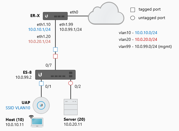
네트워크 토폴로지는 아래와 같습니다. 다음 인터페이스는 EdgeSwitch (ES)와 EdgeRouter (ER)에서 사용되는 인터페이스입니다.
ER-X
- eth0 (WAN)
- eth1.10 (VIF 10) - 10.0.10.1/24
- eth1.20 (VIF 20) - 10.0.20.1/24
- eth1.99 (VIF 99) - 10.0.99.1/24
ES-8
- 0/1 (tagged) - VLAN10
- 0/1 (untagged) - VLAN99
- 0/2 (untagged) - VLAN20
- 0/7 (tagged) - VLAN10 / VLAN20 / VLAN99
UAP는 무선 네트워크인 VLAN10에 태깅합니다. UAP의 매니지먼트 트래픽은 0/1 포트에 태깅 되지 않고 입력되고 VLAN99에 도착합니다 (네이티브 VLAN). 서버는 VLAN20에 위치합니다. 각 클라이언트는 DHCP 주소를 ER에서 전달받고 모든 트래픽을 스위치에서 ER로 라우팅합니다. 자세한 EdgeSwitch에서 포트 VLAN을 설정하는 내용은 https://help.ubnt.com/hc/en-us/articles/205197630-EdgeSwitch-VLANs-and-Tagged-Untagged-Ports 를 참조하세요
Steps - VLANs 과 VIFs
이 예제에서는 ES가 기본 설정으로 동작하며 SSH 관리자 접근이 허가되어 있습니다. 가장 처음으로는 VLAN을 생성하고 각 포트에 매핑(태깅 또는 언태깅)하는 과정이 필요합니다. 이후에는 VIF와 DCHP 스코프를 ER에 설정합니다.
 CLI 명령어: 스위치의 커맨드라인 인터페이스에 접근하세요. 콘솔 포트나 SSH/Telnet 프로그램인 PuTTY를 사용하여 접근이 가능합니다.
- VLAN 매니지먼트를 위한 네트워크 프로토콜(파라미터, VLAN-id)을 정의합니다.
network protocol none
network parms 10.0.99.2 255.255.255.0 10.0.99.1
network mgmt_vlan 99
- VLAN을 생성합니다
vlan database
 vlan 10,20,99
 exit
3. 설정모드로 진입합니다.
configure
- 위에서 생성한 VLAN에 포트를 할당합니다.
아래의 설정은 포트 0/2를 VLAN20에서, 0/3을 VLAN10(pvid)에서 해제합니다. 포트 0/1은 VLAN10 (tagging)에 네이티브 VLAN (pvid)인 VLAN99로 태깅합니다. 이후에는 필요없는 VLAN을 포트에서 제외합니다.
interface 0/1
 description UAP
 vlan tagging 10
 vlan pvid 99
 vlan participation exclude 1,20
 vlan participation include 10,99
 exit

interface 0/2
 description Server
 vlan pvid 20
 vlan participation exclude 1,10,99
 vlan participation include 20
 exit

interface 0/7
 description ER-X
 vlan tagging 10,20,99
 vlan participation exclude 1
 vlan participation include 10,20,99
 exit

GUI로 설정하는 방법: 스위치의 웹 관리 포탈로 접속합니다.
1. VLAN 관리를 위한 네트워크 프로토콜(파라미터, VLAN-id)을 정의합니다.
System > Connectivity > IPv4
Network Configuration Protocol: None
IP Address: 10.0.99.2
Subnet Mask: 255.255.255.0
Default Gateway: 10.0.99.1
Management VLAN ID: 99
- VLAN을 생성합니다.
Basic > VLAN > VLAN Wizard > Add VLAN
Enter 10,20,99 and select 'Add'
3. VLAN 위자드를 통해서 생성한 VLAN에 포트를 할당합니다.
Port 0/1: Excluded (E) for VLAN1 / VLAN20
Port 0/1: Untagged (U) for VLAN99
Port 0/1: Tagged (T) for VLAN10

Port 0/2: Excluded (E) for VLAN1 / VLAN10 / VLAN99
Port 0/2: Untagged (U) for VLAN20

Port 0/7: Excluded (E) for VLAN1
Port 0/7: Tagged (T) for VLAN10 / VLAN20 / VLAN99
 CLI 명령어: 라우터의 커맨드라인 인터페이스에 접근하여 작업합니다. 작업을 위해서는 GUI 상에서의 CLI 버튼을 클릭하거나 PuTTY와 같은 프로그램을 사용하여 접근이 가능합니다.
1. 설정 모드로 진입합니다.
configure
- 802.1Q태그를 할당한 VIF를 IP 주소를 할당하여 생성합니다.
set interfaces ethernet eth1 vif 10 address 10.0.10.1/24
set interfaces ethernet eth1 vif 20 address 10.0.20.1/24
set interfaces ethernet eth1 vif 99 address 10.0.99.1/24
- 관련된 VLAN에 DHCP 범위를 생성합니다.
set service dhcp-server shared-network-name VLAN10 subnet 10.0.10.0/24 default-router 10.0.10.1
set service dhcp-server shared-network-name VLAN10 subnet 10.0.10.0/24 dns-server 10.0.20.11
set service dhcp-server shared-network-name VLAN10 subnet 10.0.10.0/24 lease 86400
set service dhcp-server shared-network-name VLAN10 subnet 10.0.10.0/24 start 10.0.10.11 stop 10.0.10.150

set service dhcp-server shared-network-name VLAN20 subnet 10.0.20.0/24 default-router 10.0.20.1
set service dhcp-server shared-network-name VLAN20 subnet 10.0.20.0/24 dns-server 10.0.20.11
set service dhcp-server shared-network-name VLAN20 subnet 10.0.20.0/24 lease 86400
set service dhcp-server shared-network-name VLAN20 subnet 10.0.20.0/24 start 10.0.20.11 stop 10.0.20.150

set service dhcp-server shared-network-name VLAN99 subnet 10.0.99.0/24 default-router 10.0.99.1
set service dhcp-server shared-network-name VLAN99 subnet 10.0.99.0/24 dns-server 10.0.20.11
set service dhcp-server shared-network-name VLAN99 subnet 10.0.99.0/24 lease 86400
set service dhcp-server shared-network-name VLAN99 subnet 10.0.99.0/24 start 10.0.99.11 stop 10.0.99.150
- 변경사항을 커밋합니다.
commit
- 설정을 저장합니다.
save

GUI로 설정하기: 라우터의 웹 관리 포탈로 접속합니다.
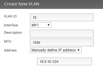
1. 802.1Q 태그를 할당한 VIF를 IP 주소와 함께 생성합니다.
Dashboard > Add Interface > Add VLAN
VLAN ID: 10
Interface: eth1
Address: Manually define IP address
10.0.10.1/24

VLAN ID: 20
Interface: eth1
Address: Manually define IP address
10.0.20.1/24

VLAN ID: 99
Interface: eth1
Address: Manually define IP address
10.0.99.1/24
- 관련 VLAN에 DHCP 범위를 생성합니다.
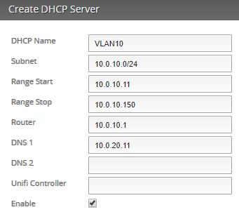
Services > DHCP Server > Add DHCP Server
DHCP Name: VLAN10
Subnet: 10.0.10.0/24
Range Start: 10.0.10.11
Range Stop: 10.0.10.150
Router: 10.0.10.1
DNS 1: 10.0.20.11

DHCP Name: VLAN20
Subnet: 10.0.20.0/24
Range Start: 10.0.20.11
Range Stop: 10.0.20.150
Router: 10.0.20.1
DNS 1: 10.0.20.11

DHCP Name: VLAN99
Subnet: 10.0.99.0/24
Range Start: 10.0.99.11
Range Stop: 10.0.99.150
Router: 10.0.99.1
DNS 1: 10.0.20.11
Steps - 방화벽 룰
이전 단계에서 설정을 하고 난 이후에는 모든 VLAN 사이에서 양방향 통신이 이루어집니다. EdgeRouter에 연결된 VIF가 0/7 포트에 할당되어있기 떄문입니다. 게스트 계정은 UniFi SSID 로 접근하여 VLAN10 의 DHCP 주소를 받게 됩니다.
다음 단계는 VLAN10 호스트로 접근하는 커뮤니케이션을 제한하는 단계입니다. 커뮤니케이션을 특정 목적지로 가도록 제한하기 위해서는 다음의 사항이 필요합니다.
- VLAN10에서 VLAN20, VLAN99로 이동하는 무선 트래픽을 차단합니다. 10.0.20.11 서버로 향하는 DNS 트래픽은 예외 처리합니다.
- ER 인터페이스로 가는 무선 호스트의 모든 트래픽을 차단합니다.
- 10.0.10.1 ER에서 무선 호스트의 DCHP 주소를 얻는 요청은 허용합니다.
- VLAN10에서 무선 호스트가 위에 명시한 다른 목적지를 향하는 트래픽은 모두 허용합니다.
 CLI 설정방법: 라우터의 커맨드라인 인터페이스에 접속합니다. GUI의 CLI 버튼을 클릭하거나, PuTTY와 같은 프로그램을 사용하여 접속합니다.
- 할당된 DCHP leases가 클라이언트에서 접근이 가능한지 확인합니다.
show dhcp leases
IP address      Hardware Address   Lease expiration     Pool       Client Name
----------      ----------------   ----------------     ----       -----------
10.0.10.11      80:2a:a8:f5:69:f1  2017/07/02 08:40:10  VLAN10     Host
10.0.20.11      80:2a:a8:a5:a8:99  2017/07/02 08:39:42  VLAN20     Server
10.0.99.11      80:2a:a8:99:92:d5  2017/07/02 07:46:21  VLAN99     UAP
- 설정모드로 진입합니다.
configure
- RFC1918 주소 공간에 해당하는 방화벽 네트워크 그룹을 생성합니다.
set firewall group network-group PRIVATE_NETS network 192.168.0.0/16
set firewall group network-group PRIVATE_NETS network 172.16.0.0/12
set firewall group network-group PRIVATE_NETS network 10.0.0.0/8
- 요구사항 1과 4를 만족하는 방화벽 룰을 생성합니다.
set firewall name GUEST_IN default-action accept

set firewall name GUEST_IN rule 10 action accept
set firewall name GUEST_IN rule 10 description 'Allow guests DNS'
set firewall name GUEST_IN rule 10 log disable
set firewall name GUEST_IN rule 10 protocol tcp_udp
set firewall name GUEST_IN rule 10 destination address 10.0.20.11
set firewall name GUEST_IN rule 10 destination port 53

set firewall name GUEST_IN rule 20 action drop
set firewall name GUEST_IN rule 20 description 'Drop guests to other LANs'
set firewall name GUEST_IN rule 20 log disable
set firewall name GUEST_IN rule 20 protocol all
set firewall name GUEST_IN rule 20 destination group network-group PRIVATE_NETS
- 요구사항 2와 3를 만족하는 방화벽 룰을 생성합니다.
set firewall name GUEST_LOCAL default-action drop

set firewall name GUEST_LOCAL rule 10 action accept
set firewall name GUEST_LOCAL rule 10 description DHCP
set firewall name GUEST_LOCAL rule 10 log disable
set firewall name GUEST_LOCAL rule 10 protocol udp
set firewall name GUEST_LOCAL rule 10 destination port 67
- 인바운드와 로컬 네트워크에 속한 인터페이스인 VIF10 에 방화벽 룰을 적용합니다.
set interfaces ethernet eth1 vif 10 firewall in name GUEST_IN
set interfaces ethernet eth1 vif 10 firewall local name GUEST_LOCAL

Note
inbound 에 속하는 방화벽 룰은 디바이스로 전달됩니다. 본 예제에서는 VLAN10에서 다른 VLAN이나 인터넷으로 통하는 트래픽입니다. local 에 속하는 방화벽 룰은 EdgeRouter로 통하는 DHCP 요청과 같은 관리 트래픽을 설정합니다.
 GUI로 설정하기: 라우터의 웹 관리 포탈로 접속합니다.
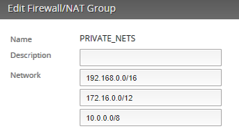
- RFC1918 주소 공간에 해당하는 방화벽 네트워크 그룹을 생성합니다.
Firewall/NAT > Firewall/NAT Groups > Add Group
Name: PRIVATE_NETS
Group Type: Network
Firewall/NAT > Firewall/NAT Groups > PRIVATE_NETS > Actions > Config > + Add New
Network: 192.168.0.0/16
Network: 172.16.0.0/12
Network: 10.0.0.0/8
 |
- 요구사항 1과 4를 만족하는 방화벽 룰을 생성합니다.
Firewall/NAT > Firewall Policies > + Add Ruleset
Name: GUEST_IN
Default action: Accept
Firewall/NAT > Firewall Policies > GUEST_IN > Actions > Edit Ruleset > + Add New Rule
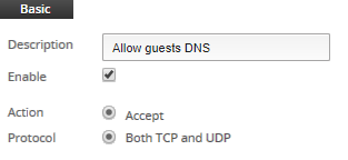
Description: Allow guests DNS
Action: Accept
Protocol: Both TCP and UDP
Destination Address: 10.0.20.11
Destination Port: 53

Firewall/NAT > Firewall Policies > GUEST_IN > Actions > Edit Ruleset > + Add New Rule
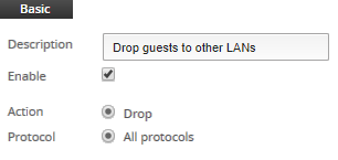
Description: Drop guests to other LANs
Action: Drop
Protocol: All protocols
Destination Network Group: PRIVATE_NETS

- 요구사항 2와 3를 만족하는 방화벽 룰을 생성합니다.
Firewall/NAT > Firewall Policies > + Add Ruleset
Name: GUEST_LOCAL
Default action: Drop
Firewall/NAT > Firewall Policies > GUEST_LOCAL > Actions > Edit Ruleset > + Add New Rule
Description: DHCP
Action: Accept
Protocol: UDP
Destination Port: 67
- 인바운드와 로컬 네트워크에 속한 인터페이스인 VIF10 에 방화벽 룰을 적용합니다.
Firewall/NAT > Firewall Policies > GUEST_IN > Actions > Interfaces
Interface: eth1.10
Direction: in
Firewall/NAT > Firewall Policies > GUEST_LOCAL > Actions > Interfaces
Interface: eth1.10
Direction: local
Steps - 테스트 및 검증
VLAN과 포트를 설정하고 난 이후에는 커넥션과 상태가 유지되는지 다음 명령어를 입력하여 검증합니다:
- 스위치포트 인터페이스 (ES)의 VLAN 포트 상태:
show interfaces switchport general
Intf      PVID  Ingress    Acceptable Untagged  Tagged    Forbidden Dynamic
               Filtering  Frame Type Vlans     Vlans     Vlans     Vlans
--------- ----- ---------- ---------- --------- --------- --------- ---------
0/1       99    Disabled   Admit all  99        10        1,20
0/2       20    Disabled   Admit all  20                  1,10,99
0/7       1     Disabled   Admit all            10,20,99  1

show interfaces switchport 0/1
VLAN Membership Mode: General
General Mode PVID: 99
General Mode Untagged VLANs: 99
General Mode Tagged VLANs: 10
General Mode Forbidden VLANs: 1,20

show interfaces switchport 0/2
VLAN Membership Mode: General
General Mode PVID: 20
General Mode Untagged VLANs: 20
General Mode Tagged VLANs:
General Mode Forbidden VLANs: 1,10,99

show interfaces switchport 0/7
Port: 0/7
VLAN Membership Mode: General
General Mode PVID: 1 (default)
General Mode Untagged VLANs:
General Mode Tagged VLANs: 10,20,99
General Mode Forbidden VLANs: 1
- ER의 VIF:
show interfaces
Codes: S - State, L - Link, u - Up, D - Down, A - Admin Down
Interface    IP Address                        S/L  Description
---------    ----------                        ---  -----------
eth1         -                                 u/u
eth1.10      10.0.10.1/24                      u/u
eth1.20      10.0.20.1/24                      u/u
eth1.99      10.0.99.1/24                      u/u
- ER의 게스트 방화벽 정책 통계:
show firewall name GUEST_IN statistics
--------------------------------------------------------------------------------

IPv4 Firewall "GUEST_IN"

Active on (eth1.10,IN)

rule  packets     bytes       action  description
----  -------     -----       ------  -----------
10    73          4507        ACCEPT  Allow guests DNS
20    6           360         DROP    Drop guests to other LANs
10000 8           480         ACCEPT  DEFAULT ACTION


show firewall name GUEST_LOCAL statistics
--------------------------------------------------------------------------------

IPv4 Firewall "GUEST_LOCAL"


Active on (eth1.10,LOCAL)

rule  packets     bytes       action  description
----  -------     -----       ------  -----------
10    56          18962       ACCEPT  DHCP
10000 464         60602       DROP    DEFAULT ACTION
- ER에 요청되는 VLAN 10 DHCP 요청:
sudo tcpdump -i eth1.10 -n host 10.0.10.11 and dst port 53 or port 67 or port 68
tcpdump: verbose output suppressed, use -v or -vv for full protocol decode
listening on eth1, link-type EN10MB (Ethernet), capture size 262144 bytes
IP 0.0.0.0.68 > 255.255.255.255.67: BOOTP/DHCP, Request from 00:0c:29:00:80:dc, length 331
IP 10.0.10.1.67 > 10.0.10.11.68: BOOTP/DHCP, Reply, length 300
IP 10.0.10.11.1058 > 10.0.20.11.53: 1+ PTR? 11.20.0.10.in-addr.arpa. (41)
IP 10.0.10.11.1059 > 10.0.20.11.53: 2+ A? server.ubnt.com. (33)
- 게스트가 다른 목적지 (인터넷)으로 접근이 가능한가:
show nat translations
Pre-NAT              Post-NAT             Type  Prot  Timeout
10.0.10.11           203.0.113.1          snat  icmp  2
관련문서