EdgeRouter - RADIUS를 활용한 IPsec L2TP 서버
download at 2017-09-22T21:49:49Z origin
Overview
이 문서는 RADIUS 인증방식을 활용하여 EdgeRouter를 L2TP (레이어 2 터널링 프로토콜)로 구성하는 방법에 대하여 서술합니다. L2TP IPsec VPN 서버 문서를 참조하여 L2TP 서버를 구성하는 방법에 대하여 확인하십시오. 이 문서는 'pre-shared-secret' 인증 방식을 기반으로 하며, 'certificate-based' 인증 방식을 사용하지 않습니다.
 Notes & Requirements: 1.9.7 EdgeOS 펌웨어가 설치된 모든 EdgeRouter 모델에서 도작합니다. 커맨드라인 인터페이스와 기본 네트워킹에 관한 지식이 요구되며, 해당 지식이 부족할 경우, 관련 문서 를 참조하기 바랍니다.
이 문서에서 사용한 장비:
- 피어(Host1, Server1)의 테스트 클라이언트
- 윈도우 서버 2016 네트워크 정책 서버 (NPS)
Table of Contents
네트워크 다이어그램
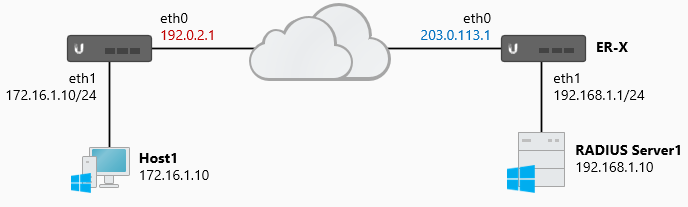
네트워크 토폴로지는 아래와 같습니다. Host1과 클라이언트 라우터가 사용하는 IP 주소와 인터페이스는 본 문서와 관련이 없습니다. L2TP 용어를 사용하여 ER-X를 'L2TP Server', Host1을 'L2TP Client'로 정의합니다.
ER에서 사용한 인터페이스는 다음과 같습니다:
- eth0 (WAN) - 203.0.113.1
- eth1 (LAN) - 192.168.1.1/24
Steps - L2TP 서버
기본 설정 위자드 를 통해서 ER를 구성하였다고 가정하며, LAN에 있는 호스트가 인터넷과 통신하기 위해서 마스커레이드 룰이 적용되었다고 가정합니다.
L2TP와 관련있는 UDP 포트와 프로토콜은 다음과 같습니다:
- UDP 1701 (L2TP)
- UDP 500 (IKE)
- ESP (프로토콜 50)
- UDP 4500 (NAT-T)
 CLI STEPS: 커맨드라인 인터페이스에 접속합니다. GUI의 CLI 버튼을 사용하거나 PuTTY와 같은 프로그램을 사용합니다.
- 환경설정 모드로 진입합니다.
configure
- 서버 인증 세팅을 설정합니다. (<secret>을 원하는 패스워드로 입력합니다)
set vpn l2tp remote-access ipsec-settings authentication mode pre-shared-secret
set vpn l2tp remote-access ipsec-settings authentication pre-shared-secret <secret>

Note
미리 공유된 비밀번호에서 '인용부호' 사용하는 경우, 클라이언트에서 같은 인용부호를 사용하지 않도록 주의하십시오 예를 들어 set vpn l2tp remote-access ipsec-settings authentication pre-shared-secret 'sup3rSecure' 는 반드시 *sup3rSecure *로 입력해야 합니다.
- VPN 클라이언트에서 사용할 IP 주소 정보를 생성합니다.
set vpn l2tp remote-access client-ip-pool start 192.168.100.240
set vpn l2tp remote-access client-ip-pool stop 192.168.100.249
Note
로컬 서브넷 IP 주소를 부여할 수도 있습니다. (192.168.1.0/24) 하지만, DHCP 서버나, 다른 장비에서 사용하는 주소와 겹치지 않게 발급해야합니다. 같은 범위 안에 있는 주소를 정의하는 것은 멀티캐스트를 수행할 우려가 있기 때문에 권장하지 않습니다.
- DPN 클라이언트가 사용할 DNS 서버를 정의합니다.
set vpn l2tp remote-access dns-servers server-1 8.8.8.8
set vpn l2tp remote-access dns-servers server-2 8.8.4.4
라우터의 내부 IP를 DNS 서버로 정의할 수 있습니다. 해당 경우에는 DNS 포워딩을 사용하고, 같은 내부 IP를 수신 주소로 설정해야합니다.
set vpn l2tp remote-access dns-servers server-1 192.168.1.1
set service dns forwarding options "listen-address=192.168.1.1"
set service dns forwarding cache-size 150
set service dns forwarding listen-on eth1
- 클라이언트로부터 L2TP 요청을 받을 WAN 인터페이스를 정의합니다.
다음 중 하나의 구문만 수행하십시오. 어느 것이 가장 좋을지는 본인의 환경에 맞는 것으로 합니다:
- DHCP를 통해서 WAN 주소를 부여 받는다.
set vpn l2tp remote-access dhcp-interface eth0
- WAN 인터페이스가 고정 주소를 할당한 경우. (외부 주소 값을 변경합니다)
set vpn l2tp remote-access outside-address 203.0.113.1
- WAN 인터페이스가 PPPoE를 사용하여 주소를 부여 받거나 듀얼 WAN 로드 밸런싱을 사용하는 경우.
set vpn l2tp remote-access outside-address 0.0.0.0
Note
다중 업링크를 사용하는 경우에는 Option C를 사용하십시오. A나 B는 L2TP 서버가 단일 WAN 주소만 접근이 가능합니다.
- RADIUS 인증 방식을 설정합니다. (<secret>을 원하는 비밀번호로 변경합니다.)
set vpn l2tp remote-access authentication mode radius
set vpn l2tp remote-access authentication radius-server 192.168.1.10 key <secret>
- (선택사항) IPsec 인터페이스가 L2TP를 사용하도록 정의합니다.
이 단계는 펌웨어 버전에 의존적입니다. 공식적으로는 해당 명령어는 1.8.5 버전부터 사용 자제를 권고 합니다. 더 많은 정보는 EdgeMAX EdgeRouter software release v1.8.5 문서의 'Enhancements and bug fixes' 섹션을 참고하십시오.
set vpn ipsec ipsec-interfaces interface eth0
- (선택사항) L2TP 트래픽의 MTU 값을 낮춥니다.
MTU 값을 낮추게 되면 L2TP 터널 성능이 낮아집니다. 예제 경우는 외부 WAN 인터페이스가 PPPoE를 사용하는 경우입니다. (1492 byte MTU)
set vpn l2tp remote-access mtu <mtu-value>
- (선택사항) 연결 될 때 VPn 클라이언트에 특정 인증방식을 요청하도록 합니다.
set vpn l2tp remote-access authentication require [ pap | chap | mschap | mschap-v2 ]
- PAP - 패스워드 인증 프로토콜 요청
- CHAP - 챌린지 핸드셰이크 인증 프로토콜 요청
- MS-CHAP - 마이크로소프트 챌린지 핸드셰이크 인증방식 프로토콜 요청
- MS-CHAP-V2 - 마이크로소프트 챌린지 핸드셰이크 인증방식 버전2 프로토콜 요청
- 변경사항을 커밋합니다.
commit
- 환경설정을 저장합니다.
save
Steps - 방화벽 룰
기본 설정 위자드 를 통해서 생성한 WAN_LOCAL 룰은 기본 값으로 모든 수신 커넥션에 대하여 허용하지 않습니다. L2TP, ESP, IKE 방화벽 룰은 VPN 트래픽을 허용하기 위해 룰을 조정해야합니다.
- 환경설정 모드로 진입합니다.
configure
- WAN 인터페이스에 L2TP, IKE, NAT-T, ESP 방화벽 룰을 추가합니다.

Attention
방화벽 룰이 기존의 룰을 덮어쓰지 않도록 주의하십시오. show firewall name WAN_LOCAL **명령어를 수행하거나 **Firewall / NAT > Firewall Policies > WAN_LOCAL > Actions > Edit Ruleset 를 GUI 상에서 수행하여 확인하십시오.
set firewall name WAN_LOCAL rule 30 action accept
set firewall name WAN_LOCAL rule 30 description IKE
set firewall name WAN_LOCAL rule 30 destination port 500
set firewall name WAN_LOCAL rule 30 log disable
set firewall name WAN_LOCAL rule 30 protocol udp

set firewall name WAN_LOCAL rule 40 action accept
set firewall name WAN_LOCAL rule 40 description L2TP
set firewall name WAN_LOCAL rule 40 destination port 1701
set firewall name WAN_LOCAL rule 40 log disable
set firewall name WAN_LOCAL rule 40 protocol udp

set firewall name WAN_LOCAL rule 50 action accept
set firewall name WAN_LOCAL rule 50 description ESP
set firewall name WAN_LOCAL rule 50 log disable
set firewall name WAN_LOCAL rule 50 protocol esp

set firewall name WAN_LOCAL rule 60 action accept
set firewall name WAN_LOCAL rule 60 description NAT-T
set firewall name WAN_LOCAL rule 60 destination port 4500
set firewall name WAN_LOCAL rule 60 log disable
set firewall name WAN_LOCAL rule 60 protocol udp
Note
WAN 인터페이스에 적용하는 로컬 방화벽 룰은 환경에 따라 다를 수 있습니다. 어떤 네이밍 규칙을 사용하든 관련 없이 올바른 방화벽룰을 적용해야 합니다. **set interfaces ethernet eth0 firewall local name <firewall name> **구문을 사용하여 직접 적용할 수도 있습니다.
- 변경내역을 커밋한다.
commit
- 환경설정을 저장한다.
save
Steps - RADIUS 서버
아래의 내용은 윈도우 2016 서버의 네트워크 정책과 접근 서비스에 대하여 서술합니다. 온라인에 자세한 내용을 다루는 문서가 많으니 해당 문서를 참조하십시오.
- NPS role을 추가합니다.
Server Manager > Add Roles and Features > Network Policy and Access Services
- EdgeRouter에 RADIUS 클라이언트를 추가합니다. (<secret>을 원하는 비밀번호로 변경하세요.)
Network Policy Server Console (NPS) > Radius Clients and Servers > Radius Clients > New
Friendly Name: ER-X (does not have to match device hostname)
Address (IP or DNS): 192.168.1.1 (the source address of the router)
Shared Secrets Template: None
Shared Secret: Manual
Shared Secret / Confirm: <secret>
Note
'RADIUS Shared Secret Template'을 사용하여 공통 패스워드를 정의할 수 있습니다.
- RADIUS 클라이언트를 위한 네트워크 정책을 생성합니다.
NPS > Policies > Network Policy > New
Policy Name: ER Radius Clients
Type of Network Access Server: Unspecified
Specify Conditions > Add
Client Friendly Name: ER-?
User Groups: UBNT\Network Engineers
Note
활성 디렉토리 (AD)나 로컬 사용자 인증을 사용할수도 있습니다. 이 예제에서는 사용자가 ER에 인증하기 위해서 UBNT 도메인에 '네트워크 엔지니어'로 인증을 수행합니다. 사용자에게 익숙한 이름을 매칭 표현식으로 정의할 수 있습니다. 'ER-?'은 'ER-'로 시작하는 문자열에 대하여 검사를 수행합니다.
Next > Specify Access Permission
Access Granted
Next > Configure Authentication Methods
Uncheck all methods and check ‘Microsoft Encrypted Authentication Version 2 (MS-CHAP-v2)’
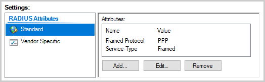
Next > Configure Constraints > Next > Configure Settings > Radius Attributes: Standard
Framed-Protocol: PPP
Service-Type: Framed
Steps - 윈도우 클라이언트
다수의 애플리케이션과 운용체제를 사용하여 L2TP 서버에 연결하는 방법은 다양합니다. 이 문서에서는 Windows 10 VPN 클라이언트에 집중하여 설명합니다. 가장 많이 사용되는 클라이언트이기 때문에 해당 클라이언트에 대하여 설명합니다.
- Windows 10 Settings (WIN+I) > Network & Internet > Add a VPN connection 으로 이동합니다.
- VPN Provider: Windows (built-in)
- Connection name: ER-L2TP
- Server name: Your ER external WAN IP-address
- VPN Type: L2TP/IPsec with pre-shared key or certificate
- Windows 10 Network Connections (WIN+X) > ER-L2TP Adapter properties 로 이동합니다.
Security > Allow these protocols > Microsoft CHAP Version 2 (MS-CHAP v2)
Note
L2TP서버로 연결할 수 없다면, 윈도우 운용체제에서 연결을 차단하고 있거나 IPsec 트래픽이 관리되고 있음을 뜻합니다. step 3의 핫픽스를 적용하십시오.
3.  (핫픽스) Windows10 registry (WIN+R) > regedit 으로 이동합니다.
다음 레지스트리 서브 트리로 이동합니다:
HKEY_LOCAL_MACHINE\SYSTEM\CurrentControlSet\Services\PolicyAgent
새로운 DWORD (32-bit) 를 생성합니다:
AssumeUDPEncapsulationContextOnSendRule
이 DWORD 값을 2로 변경하고, 컴퓨터를 재시작합니다.
Steps - 테스트 및 검증
L2TP 트래픽이 올바르게 도착하는지 검증하기 위해서는 로그를 확인해야 합니다. L2TP VPN에 문제가 있다면 로그 파일을 확인하여 문제를 확인하십시오. L2TP 세션이 생성되고나면, 다음 명령어를 RADIUS 서버에 실행하여 연결을 검증합니다:
- UDP 포트 (1812)로 수신, 송신하는 요청:
sudo tcpdump -i eth1 -n -vv udp dst port 1812
tcpdump: listening on eth1, link-type EN10MB (Ethernet), capture size 262144 bytes
17:15:08.874836 IP (tos 0x0, ttl 64, id 0, offset 0, flags [DF], proto UDP (17), length 161)
 192.168.1.1.37642 > 192.168.1.10.1812: [udp sum ok] RADIUS, length: 133
 Access-Request (1), id: 0x91, Authenticator: 522ab5d069e26abc7782f7433119a087
 Service-Type Attribute (6), length: 6, Value: Framed
 0x0000: 0000 0002
 Framed-Protocol Attribute (7), length: 6, Value: PPP
 0x0000: 0000 0001
 User-Name Attribute (1), length: 7, Value: user1
 0x0000: 7573 6572 31
 Vendor-Specific Attribute (26), length: 24, Value: Vendor: Microsoft (311)
 Vendor Attribute: 11, Length: 16, Value: X.wN......aDn4.o
 0x0000: 0000 0137 0b12 58eb 774e 0690 81c9 b38a
 0x0010: 6144 6e34 e66f
 Vendor-Specific Attribute (26), length: 58, Value: Vendor: Microsoft (311)
 Vendor Attribute: 25, Length: 50, Value: ...TT........_..............A..+..4Y.....X.u.._...
 0x0000: 0000 0137 1934 f300 0954 54e8 87a6 8cc1
 0x0010: cbeb 865f 1006 00f2 0000 0000 0000 0000
 0x0020: a7c2 41f4 cb2b 921a 3459 9eed 8792 d358
 0x0030: 8d75 b188 5f99 1aa7
 NAS-IP-Address Attribute (4), length: 6, Value: 127.0.1.1
 0x0000: 7f00 0101
 NAS-Port Attribute (5), length: 6, Value: 0
 0x0000: 0000 0000
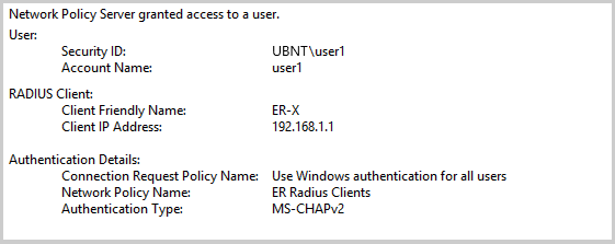
- RADIUS 서버의 이벤트 로그:
Event Viewer > Custom Views > ServerRoles > Network Policy and Access Services
3. PPPD 관련 로그를 확인하기 위한 임시 로그 파일 생성:
set system syslog file radiustemporary facility all level debug
commit

run show log file radiustemporary
Jul 14 17:25:09 ubnt xl2tpd[2532]: Connection established to 192.0.2.1, 1701. Local: 26356, Remote: 19 (ref=0/0)
Jul 14 17:25:09 ubnt xl2tpd[2532]: Call established with 192.0.2.1, Local: 35889, Remote: 1, Serial: 0
Jul 14 17:25:09 ubnt pppd[7138]: Using interface ppp0
Jul 14 17:25:09 ubnt pppd[7138]: sent [LCP ConfReq id=0x2 <asyncmap 0x0> <auth chap MS-v2> <magic 0x5c8d6fbe>]
Jul 14 17:25:09 ubnt pppd[7138]: rcvd [LCP ConfAck id=0x2 <asyncmap 0x0> <auth chap MS-v2> <magic 0x5c8d6fbe>]
Jul 14 17:25:11 ubnt pppd[7138]: lcp_reqci: returning CONFACK.
Jul 14 17:25:11 ubnt pppd[7138]: sent [CHAP Challenge id=0x8a <5820432807b27bbc5a6be3870cad28f8>, name = "xl2tpd"]
Jul 14 17:25:11 ubnt pppd[7138]: rcvd [CHAP Response id=0x8a <d0f635e2ded9bc5058731d63455fa2a00>, name = "user1"]
Jul 14 17:25:11 ubnt pppd[7138]: sent [CHAP Success id=0x8a "S=2C2B5E6678413055975930084A5B27D78DEA339D"]
Jul 14 17:25:11 ubnt pppd[7138]: sent [IPCP ConfNak id=0x9 <addr 192.168.100.240>]
Jul 14 17:25:11 ubnt pppd[7138]: rcvd [IPCP ConfReq id=0xa <addr 192.168.100.240>]
Jul 14 17:25:11 ubnt pppd[7138]: ipcp: returning Configure-ACK
Jul 14 17:25:11 ubnt pppd[7138]: ipcp: up

delete system syslog file radiustemporary
commit
- ER에서 IPsec 프로세스의 상태 확인하기:
sudo ipsec statusall
Status of IKE charon daemon (strongSwan 5.2.2, Linux 3.10.14-UBNT, mips):
 uptime: 49 seconds, since Jul 17 14:01:59 2017
 malloc: sbrk 376832, mmap 0, used 272072, free 104760
 worker threads: 11 of 16 idle, 5/0/0/0 working, job queue: 0/0/0/0, scheduled: 0
Listening IP addresses:
 192.168.1.1
 203.0.113.1
 10.255.255.0
Connections:
remote-access: 203.0.113.1...%any IKEv1, dpddelay=15s
remote-access: local: [203.0.113.1] uses pre-shared key authentication
remote-access: remote: uses pre-shared key authentication
remote-access: child: dynamic[udp/l2f] === dynamic[udp] TRANSPORT, dpdaction=clear
Security Associations (1 up, 0 connecting):
remote-access[1]: ESTABLISHED 30 seconds ago, 203.0.113.1[203.0.113.1]...192.0.2.1[172.16.1.10]
remote-access[1]: IKEv1 SPIs: 7ef8fd033bea7f4c_i 27eaafddd951c8dc_r*, rekeying disabled
remote-access[1]: IKE proposal: AES_CBC_256/HMAC_SHA1_96/PRF_HMAC_SHA1/ECP_384
remote-access{1}: INSTALLED, TRANSPORT, ESP in UDP SPIs: c009fce1_i cd73f1b4_o
remote-access{1}: AES_CBC_128/HMAC_SHA1_96, 3594 bytes_i (36 pkts, 18s ago), 675 bytes_o (17 pkts, 27s ago)
remote-access{1}: 203.0.113.1/32[udp/l2f] === 192.0.2.1/32[udp/l2f]
Note
커넥션이 연결되지 않는다면, IPsec 프로세스를 sudo ipsec restart 를 실행하여 다시 시작합니다.
5. 트래픽이 방화벽 룰에 따라서 카운터 값을 증가시키는지 확인합니다.
show firewall name WAN_LOCAL statistics
------------------------------------------
IPv4 Firewall "WAN_LOCAL" [WAN to router]
 Active on (eth0,LOCAL)

rule   packets  bytes   action   description
----   -------  -----   ------   -----------
10     2926     271414  ACCEPT   Allow established/related
20     0        0 DROP  Drop     invalid state
30     19       5512    ACCEPT   IKE
40     5        655     ACCEPT   L2TP
50     0        0       ACCEPT   ESP
60     8        1088    ACCEPT   NAT-T
10000  69       9516    DROP     DEFAULT ACTION
- ER 외부 WAN 인터페이스에서 L2TP 트래픽을 감지하는지 확인합니다:
sudo tcpdump -i eth0 -n udp dst port 500 or port 4500 or port 1701
tcpdump: verbose output suppressed, use -v or -vv for full protocol decode
listening on eth0, link-type EN10MB (Ethernet), capture size 262144 bytes
IP 192.0.2.1.500 > 203.0.113.1.500: isakmp: phase 1 I ident
IP 203.0.113.1.500 > 192.0.2.1.500: isakmp: phase 1 R ident
IP 192.0.2.1.500 > 203.0.113.1.500: isakmp: phase 1 I ident
IP 203.0.113.1.500 > 192.0.2.1.500: isakmp: phase 1 R ident
IP 192.0.2.1.4500 > 203.0.113.1.4500: NONESP-encap: isakmp: phase 1 I ident[E]
IP 203.0.113.1.4500 > 192.0.2.1.4500: NONESP-encap: isakmp: phase 1 R ident[E]
IP 192.0.2.1.4500 > 203.0.113.1.4500: NONESP-encap: isakmp: phase 2/others I oakley-quick[E]
IP 203.0.113.1.4500 > 192.0.2.1.4500: NONESP-encap: isakmp: phase 2/others R oakley-quick[E]
IP 192.0.2.1.4500 > 203.0.113.1.4500: NONESP-encap: isakmp: phase 2/others I oakley-quick[E]
IP 192.0.2.1.4500 > 203.0.113.1.4500: UDP-encap: ESP(spi=0xc009fce1,seq=0x1), length 164
IP 192.0.2.1.4500 > 203.0.113.1.4500: UDP-encap: ESP(spi=0xc009fce1,seq=0x2), length 164
Note
위의 결과는 실시간 캡쳐의 결과 입니다. 아무런 결과도 관찰할 수 없다면, 트래픽이 생성되지 않았거나 트래픽 업스트림이 차단당했을 수 있습니다. 출력이 생성되었는데 커넥션이 만들어지지 않았다면, 방화벽 룰을 확인해 보십시오.
7. ER IPsec VPN 로그를 확인합니다:
sudo swanctl --log
[NET] received packet: from 192.0.2.1[500] to 203.0.113.1[500] (408 bytes)
[IKE] 192.0.2.1 is initiating a Main Mode IKE_SA
[IKE] remote host is behind NAT
[CFG] looking for pre-shared key peer configs matching 203.0.113.1...192.0.2.1[172.16.0.10]
[CFG] selected peer config "remote-access"
[IKE] IKE_SA remote-access[15] established between ...
[IKE] CHILD_SA remote-access{5} established with SPIs ...
[KNL] 10.255.255.0 appeared on ppp0
Note
실시간 캡쳐의 결과이므로 방화벽을 통해서 트래픽이 받아지고 있는지 확인하십시오. show vpn log | no-more 명령어를 통해서 IPsec 로그 히스토리를 확인할 수 있습니다.
8. IPsec 보안 관련(SAs) 옵션을 확인합니다:
show vpn ipsec sa
remote-access: #545, ESTABLISHED, IKEv1, b0a8c5df5ff1b225:a251946b15ebaaae
 local '203.0.113.1' @ 203.0.113.1
 remote '172.16.0.10' @ 192.0.2.1
 AES_CBC-256/HMAC_SHA1_96/PRF_HMAC_SHA1/ECP_384
 established 351s ago
 remote-access: #17, INSTALLED, TRANSPORT-in-UDP, ESP:AES_CBC-128/HMAC_SHA1_96
 installed 8 ago
 in cd49a319, 0 bytes, 0 packets
 out 47a8a786, 0 bytes, 0 packets
 local 76.237.8.193/32[udp/l2f]
 remote 192.0.2.1/32[udp/l2f]
9. 원격 접속 사용자와 인터페이스를 확인합니다:
show vpn remote-access
Active remote access VPN sessions:

User       Time      Proto Iface Remote IP       TX pkt/byte   RX pkt/byte
---------- --------- ----- ----- --------------- ------ ------ ------ ------
ubnt       00h01m22s L2TP  l2tp0 192.168.100.240     4     58     86   7.4K

show interfaces
Codes: S - State, L - Link, u - Up, D - Down, A - Admin Down
Interface   IP Address    S/L   Description
---------   ----------    ---   -----------
l2tp0       10.255.255.0  u/u   User: ubnt (192.168.100.240)
10. 터널로 트래픽을 Host1 과 Server1 사이에서 주고받습니다:
ping 192.168.1.10
PING 192.168.1.10 (192.168.1.10) 56(84) bytes of data.
64 bytes from 192.168.1.10: icmp_seq=1 ttl=63 time=45.9 ms
64 bytes from 192.168.1.10: icmp_seq=2 ttl=63 time=45.2 ms
64 bytes from 192.168.1.10: icmp_seq=3 ttl=63 time=45.5 ms

ping 172.16.1.10
PING 172.16.1.10 (172.16.1.10) 56(84) bytes of data.
64 bytes from 172.16.1.10: icmp_seq=1 ttl=63 time=43.9 ms
64 bytes from 172.16.1.10: icmp_seq=2 ttl=63 time=44.1 ms
64 bytes from 172.16.1.10: icmp_seq=3 ttl=63 time=44.4 ms
관련문서