EdgeRouter - LDP 시그널링 환경 설정을 활용한 기본 가상 사설 LAN 서비스 (VPLS)
download at 2017-02-07T01:01:45Z origin
Overview
이 문서에서는 시그널링 LDP와 VPLS를 사용하여 같은 레이어 2 네트워크에 있는 것 처럼 동작하게 하는 다중 사이트에 연결하는 방법에 대하여 서술합니다.
Table of Contents
시나리오
가상 사설 LAN 서비스 (VPLS)는 하나의 레이어2 네트워크에 있는 것처럼 동작하여 다중 사이트 접근을 허용하도록 하는 기능을 합니다. VPLS를 사용한 서로 다른 사이트가 기본적으로 "같은 LAN"에 있도록 하여 직접 연결 된것 처럼 보이게 합니다. 예를 들어 다음 시나리오를 고려해볼 수 있습니다:
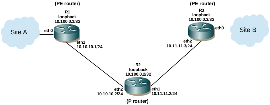
목표는 사이트 A와 B를 연결하는 것입니다. 예를 들어, R1, R2, R3가 서비스 제공자 라우터이며, R1, R3는 제공자 EdgeRouter (PE router)이고, R2는 제공자 라우터 (P router)로 고려합니다. 제공자는 VPLS를 PE 라우터에서 각 사이트에 이더넷 연결 (eth0)을 사용하여 기능을 제공합니다. VPLS, 브로드 캐스트, VLAN 등은 두 사이트 모두에서 같은 레이어 2 네트워크에 있는 것 처럼 동작하도록 할 수 있습니다.
이 문서에서는 VPLS를 위의 시나리오에서 레이블 분배 프로토콜을 시그널링을 위해 사용하여 구성합니다.
인터페이스와 OSPF 환경 설정
먼저, 인터페이스 주소, MTU, OSPF 설정을 각 라우터를 대상으로 설정합니다:
R1
set interfaces ethernet eth1 address 10.10.10.1/24
set interfaces ethernet eth1 mtu 1526
set interfaces ethernet eth0 mtu 1504
set interfaces loopback lo address 10.100.0.1/32
set protocols ospf area 0.0.0.0 network 10.0.0.0/8
R2
set interfaces ethernet eth2 address 10.10.10.2/24
set interfaces ethernet eth2 mtu 1526
set interfaces ethernet eth1 address 10.11.11.2/24
set interfaces ethernet eth1 mtu 1526
set interfaces loopback lo address 10.100.0.2/32
set protocols ospf area 0.0.0.0 network 10.0.0.0/8
R3
set interfaces ethernet eth2 address 10.11.11.3/24
set interfaces ethernet eth2 mtu 1526
set interfaces ethernet eth0 mtu 1504
set interfaces loopback lo address 10.100.0.3/32
set protocols ospf area 0.0.0.0 network 10.0.0.0/8
MTU를 사용자 측면에서 1504로 설정하였습니다. 제공자 측면에서는 1526로 설정하였습니다. 이는 LAN 트래픽에 VLAN 태깅이 순서대로 될 수 있도록 할 수 있습니다.즉, 1500 바이트 MTU를 사이트A 와 B LAN에 각각 VLAN, non-VLAN 트래픽을 허용하도록 합니다.
LDP와 VPLS 환경설정
R1
set protocols mpls interface eth1 label-switching
set protocols vpls instance vpls1 id 1 signaling ldp vpls-peer 10.100.0.3
set protocols vpls interface eth0 instance vpls1
set protocols ldp interface eth1 enable ipv4
set protocols ldp targeted-peer ipv4 10.100.0.3
set protocols ldp transport-address ipv4 10.100.0.1
R2
set protocols mpls interface eth1 label-switching
set protocols mpls interface eth2 label-switching
set protocols ldp interface eth1 enable ipv4
set protocols ldp interface eth2 enable ipv4
set protocols ldp transport-address ipv4 10.100.0.2
R3
set protocols mpls interface eth2 label-switching
set protocols vpls instance vpls1 id 1 signaling ldp vpls-peer 10.100.0.1
set protocols vpls interface eth0 instance vpls1
set protocols ldp interface eth2 enable ipv4
set protocols ldp targeted-peer ipv4 10.100.0.1
set protocols ldp transport-address ipv4 10.100.0.3
VPLS는 "PE 라우터" 에서만 설정되며, "P 라우터"에서는 필요하지 않다는 점입니다. PE 라우터는 VPLS 인스턴스가 다른 인스턴스들을 인지하고 있어야 합니다. ("full mesh" 구성이 필요합니다.)
운용 상태
"show" 명령어를 사용하여 다양한 프로코콜의 운용 상태를 확인할 수 있습니다:
R1
ubnt@ubnt:~$ show ip route ospf
IP Route Table for VRF "default"
O    *> 10.11.11.0/24 [110/11] via 10.10.10.2, eth1, 00:31:32
O    *> 10.100.0.2/32 [110/20] via 10.10.10.2, eth1, 00:31:32
O    *> 10.100.0.3/32 [110/21] via 10.10.10.2, eth1, 00:31:32
Gateway of last resort is not set

ubnt@ubnt:~$
ubnt@ubnt:~$ show ldp session
Peer IP Address           IF Name    My Role    State      KeepAlive
10.100.0.3                eth1       Passive   OPERATIONAL   30
10.100.0.2                eth1       Passive   OPERATIONAL   30
ubnt@ubnt:~$
ubnt@ubnt:~$ show mpls forwarding-table
Codes: > - selected FTN, p - stale FTN, B - BGP FTN, K - CLI FTN,
       L - LDP FTN, R - RSVP-TE FTN, S - SNMP FTN, I - IGP-Shortcut,
       U - unknown FTN
Code    FEC                 FTN-ID    Tunnel-id   Pri  Nexthop          Out-Label    Out-Intf     LSP-Type
L>      10.11.11.0/24       1         0           Yes  10.10.10.2       3            eth1         LSP_DEFAULT
L>      10.100.0.2/32       2         0           Yes  10.10.10.2       3            eth1         LSP_DEFAULT
L>      10.100.0.3/32       3         0           Yes  10.10.10.2       17           eth1         LSP_DEFAULT

ubnt@ubnt:~$
R2
ubnt@ubnt:~$ show ip route ospf
IP Route Table for VRF "default"
O    *> 10.100.0.1/32 [110/11] via 10.10.10.1, eth2, 00:32:55
O    *> 10.100.0.3/32 [110/11] via 10.11.11.3, eth1, 00:32:56
Gateway of last resort is not set

ubnt@ubnt:~$
ubnt@ubnt:~$ show ldp session
Peer IP Address           IF Name    My Role    State      KeepAlive
10.100.0.3                eth1       Passive   OPERATIONAL   30
10.100.0.1                eth2       Active    OPERATIONAL   30
ubnt@ubnt:~$
ubnt@ubnt:~$ show mpls forwarding-table
Codes: > - selected FTN, p - stale FTN, B - BGP FTN, K - CLI FTN,
       L - LDP FTN, R - RSVP-TE FTN, S - SNMP FTN, I - IGP-Shortcut,
       U - unknown FTN
Code    FEC                 FTN-ID    Tunnel-id   Pri  Nexthop          Out-Label    Out-Intf     LSP-Type
L>      10.100.0.1/32       1         0           Yes  10.10.10.1       3            eth2         LSP_DEFAULT
L>      10.100.0.3/32       2         0           Yes  10.11.11.3       3            eth1         LSP_DEFAULT

ubnt@ubnt:~$
R3
ubnt@ubnt:~$ show ip route ospf
IP Route Table for VRF "default"
O    *> 10.10.10.0/24 [110/2] via 10.11.11.2, eth2, 00:33:35
O    *> 10.100.0.1/32 [110/12] via 10.11.11.2, eth2, 00:33:34
O    *> 10.100.0.2/32 [110/11] via 10.11.11.2, eth2, 00:33:35
Gateway of last resort is not set

ubnt@ubnt:~$
ubnt@ubnt:~$ show ldp session
Peer IP Address           IF Name    My Role    State      KeepAlive
10.100.0.1                eth2       Active    OPERATIONAL   30
10.100.0.2                eth2       Active    OPERATIONAL   30
ubnt@ubnt:~$
ubnt@ubnt:~$ show mpls forwarding-table
Codes: > - selected FTN, p - stale FTN, B - BGP FTN, K - CLI FTN,
       L - LDP FTN, R - RSVP-TE FTN, S - SNMP FTN, I - IGP-Shortcut,
       U - unknown FTN
Code    FEC                 FTN-ID    Tunnel-id   Pri  Nexthop          Out-Label    Out-Intf     LSP-Type
L>      10.10.10.0/24       1         0           Yes  10.11.11.2       3            eth2         LSP_DEFAULT
L>      10.100.0.1/32       2         0           Yes  10.11.11.2       16           eth2         LSP_DEFAULT
L>      10.100.0.2/32       3         0           Yes  10.11.11.2       3            eth2         LSP_DEFAULT

ubnt@ubnt:~$
MAC 주소 학습
환경 설정이 끝나고 나면 사이트 A,B의 호스트는 같은 네트워크라고 생각하면서 통신이 가능해집니다. 예를 들어 하나의 사이트에서 DHCP서버가 다른 사이트의 클라이언트와 통신이 가능하게 됩니다. 두 사이트 사이에서 트래픽이 생성되면 운용 모드에서 "show vpls <instance_name> mac-address" 명령어를 통해 나타난 라우터들의 MAC 주소 학습이 이루어 집니다:
R1
ubnt@ubnt:~$ show vpls vpls1 mac-address

VPN-ID: 1
Port: eth0 Vlan: 100 MAC: xx:xx:xx:xx:xx:xx
Port: eth0 Vlan: 1 MAC: xx:xx:xx:xx:xx:xx
Port: eth1 Peer: 10.100.0.3 MAC: xx:xx:xx:xx:xx:xx
Port: eth1 Peer: 10.100.0.3 MAC: xx:xx:xx:xx:xx:xx

ubnt@ubnt:~$
R3
ubnt@ubnt:~$ show vpls vpls1 mac-address

VPN-ID: 1
Port: eth2 Peer: 10.100.0.1 MAC: xx:xx:xx:xx:xx:xx
Port: eth2 Peer: 10.100.0.1 MAC: xx:xx:xx:xx:xx:xx
Port: eth0 Vlan: 100 MAC: xx:xx:xx:xx:xx:xx
Port: eth0 Vlan: 1 MAC: xx:xx:xx:xx:xx:xx

ubnt@ubnt:~$
위의 예제에서는 VLAN 1 (non-VLAN)의 호스트가 VLAN 100의 다른 호스트 각각의 MAC 주소가 명령어의 수행 결과로 출력되었습니다.