EdgeRouter - WAN 로드 밸런싱과 터널
download at 2017-05-25T21:36:46Z origin
이 문서에서는 WAN 로드밸런싱과 터널에 대하여 필요한 고려사항들에 대하여 다룹니다. 설명의 간편함을 위해서 GRE 터널을 사용합니다. (암호화가 이루어지지 않은 패킷을 볼 수있기 때문에 디버깅이 쉽습니다.) 실제 동작은 다른 터널도 동일하게 동작합니다.
토폴로지:
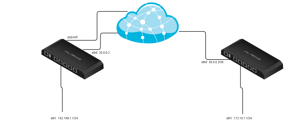
Router R1 Router R2
eth0 WAN1 20.0.0.2/30 eth0 WAN 30.0.0.2/30
eth1 LAN 192.168.1.1/24 eth1 LAN 172.16.1.1/24
pppoe0 WAN2
tun0 GRE 40.0.01/30 tun0 GRE 40.0.0.2/30
GRE 터널을 실행하고, 로드 밸런싱을 추가합니다.
R1 eth0 에서 R2 eth0로 GRE 터널을 사용하도록 합니다. 이제 R1에 다음과 같이 추가합니다:
tunnel tun0 {
    address 40.0.0.1/30
    encapsulation gre
    local-ip 20.0.0.2
    remote-ip 30.0.0.2
}
For R2:
tunnel tun0 {
    address 40.0.0.2/30
    encapsulation gre
    local-ip 30.0.0.2
    remote-ip 20.0.0.2
}
그리고 WAN_LOCAL을 위한 GRE 프로토콜을 방화벽에서 허용하도록 설정합니다.
ubnt@R1# show firewall name WAN_LOCAL rule 40
 action accept
 description "Allow GRE"
 protocol gre
 source {
     address 30.0.0.2
 }
이제 TCP mss-clamp를 사용합니다:
ubnt@R1# show firewall options
 mss-clamp {
     interface-type tun
     interface-type pppoe
     mss 1412
 }
마지막으로 R2 LAN 네트워크는 반드시 tun0 인터페이스를 사용하도록 고정 라우트를 추가합니다.
interface-route 172.16.1.0/24 {
    next-hop-interface tun0 {
    }
}
이제 GRE터널은 정상적으로 동작해야합니다 하지만 아래와 같은 결과가 발생합니다.
ubnt@R1:~$ ping 172.16.1.1
PING 172.16.1.1 (172.16.1.1) 56(84) bytes of data.
64 bytes from 172.16.1.1: icmp_req=1 ttl=64 time=0.832 ms
64 bytes from 172.16.1.1: icmp_req=2 ttl=64 time=0.741 ms
64 bytes from 172.16.1.1: icmp_req=4 ttl=64 time=0.635 ms
64 bytes from 172.16.1.1: icmp_req=5 ttl=64 time=0.654 ms
64 bytes from 172.16.1.1: icmp_req=6 ttl=64 time=0.644 ms
64 bytes from 172.16.1.1: icmp_req=7 ttl=64 time=0.614 ms
^C
--- 172.16.1.1 ping statistics ---
8 packets transmitted, 6 received, 25% packet loss, time 7006ms
rtt min/avg/max/mdev = 0.614/0.686/0.832/0.082 ms
정상 동작은 하지만 25%의 패킷 손실이 발생합니다. 가능한 이유는 2개의 인터넷 연결이 존재하기 때문에 일부 패킷이 잘못된 인터페이스로 송출될 우려가 있습니다. 이 방법을 검증하기 위해서 2번째 WAN 인터페이스를 비활성화합니다.
ubnt@R1:~$ disconnect interface pppoe0
Bringing interface pppoe0 down...
ubnt@R1:~$
ubnt@R1:~$
ubnt@R1:~$ ping 172.16.1.1
PING 172.16.1.1 (172.16.1.1) 56(84) bytes of data.
64 bytes from 172.16.1.1: icmp_req=1 ttl=64 time=0.789 ms
64 bytes from 172.16.1.1: icmp_req=2 ttl=64 time=0.606 ms
64 bytes from 172.16.1.1: icmp_req=3 ttl=64 time=0.585 ms
64 bytes from 172.16.1.1: icmp_req=4 ttl=64 time=0.667 ms
64 bytes from 172.16.1.1: icmp_req=5 ttl=64 time=0.650 ms
64 bytes from 172.16.1.1: icmp_req=6 ttl=64 time=0.707 ms
64 bytes from 172.16.1.1: icmp_req=7 ttl=64 time=0.752 ms
64 bytes from 172.16.1.1: icmp_req=8 ttl=64 time=0.613 ms
^C
--- 172.16.1.1 ping statistics ---
8 packets transmitted, 8 received, 0% packet loss, time 7007ms
rtt min/avg/max/mdev = 0.585/0.671/0.789/0.069 ms
문제가 해결되었습니다. 하지만 어떻게 2번째 WAN을 사용해야 할까요? 한가지 방법은 GRE 엔드포인트에서 강제로 eth0로 이동하도록 경로를 고정하는 것입니다.
route 30.0.0.2/32 {
    next-hop 20.0.0.1 {
    }
}
이제 pppoe0 인터페이스를 백업하고도 GRE 터널이 정상 동작하는 것을 확인할 수 있습니다.
KB의 라우터 R1, R2의 모든 환결 설정을 확인하기 위해서는 다음을 확인하십시오:
Load-Balancing
이제 R1에 WAN 로드 밸런싱을 추가합니다. load-balance 섹션부터 작성합니다:
load-balance {
    group WLB {
        interface eth0 {
        }
        interface pppoe0 {
        }
    }
}
이제 우리가 정말 필요한 작업을 수행합니다. 핑 타깃을 DNS 헬스체크가 필요하지 않는 주소로 변경합니다.
load-balance {
    group WLB {
        interface eth0 {
            route-test {
                type {
                    ping {
                        target 8.8.8.8
                    }
                }
            }
        }
        interface pppoe0 {
            route-test {
                type {
                    ping {
                        target 8.8.8.8
                    }
                }
            }
        }
    }
}
이제 방화벽 룰을 수정합니다.
modify BALANCE {
     rule 10 {
         action modify
         description "Do not load-balance LAN to LAN traffic"
         destination {
             address 192.168.1.0/24
         }
         modify {
             table main
         }
     }
     rule 20 {
         action modify
         description "load-balance the rest of LAN to WAN traffic"
         modify {
             lb-group WLB
         }
     }
 }
LAN의 "in" 수정한 정책을 적용합니다.
ethernet eth1 {
    address 192.168.1.1/24
    description LAN
    firewall {
        in {
            modify BALANCE
        }
    }
}
이제 LAN 트래픽이 양쪽 WAN 모두 동등하게 밸런싱 됩니다.
ubnt@R1:~$ show load-balance status
Group WLB
  interface   : eth0
  carrier     : up
  status      : active
  gateway     : 20.0.0.1
  weight      : 50
  flows
      WAN Out : 682
      WAN In  : 0
    Local Out : 20

  interface   : pppoe0
  carrier     : up
  status      : active
  gateway     : pppoe0
  weight      : 50
  flows
      WAN Out : 672
      WAN In  : 0
    Local Out : 22
그렇지만 GRE터널은 여전히 동작하지 않습니다. 첫번째 문제는 GRE 터널을 통하는 LAN 트래픽이 로드 밸런싱이 이루어지지 않습니다. 그러므로 lb-group 룰을 다음과 같이 추가합니다:
ubnt@R1# show firewall modify
 modify BALANCE {
     rule 10 {
         action modify
         description "Do not load-balance LAN to LAN traffic"
         destination {
             address 192.168.1.0/24
         }
         modify {
             table main
         }
     }
     rule 20 {
         action modify
         description "Do not load-balance traffic for gre tunnel"
         destination {
             address 172.16.1.0/24
         }
         modify {
             table main
         }
     }
     rule 30 {
         action modify
         description "load-balance the rest of LAN to WAN traffic"
         modify {
             lb-group WLB
         }
     }
 }
위의 룰은 대부분의 경우에서는 동작합니다. 하지만 pppoe 인터페이스를 재기동 해야 GRE 터널이 올바르게 동작할 수도 있습니다. 다음은 어떻게 로드 밸런싱 기능을 WAN 인터페이스마다 분리되어 있는 라우팅 테이블을 활용하는 가입니다. LAN에서 WAN으로 이동하는 세션은 정상 동작하지만 "main" 라우팅 테이블에서 연결 루트를 설정할 때에는 기능 동작을 하지 않을수도 있습니다. 그러므로 현재는 시스템이 생성한 라우팅 테이블을 하는 대신에 WAN과 연결된 루트를 설정하는 기본 루트를 생성합니다.
ubnt@R1# show protocols static table
 table 1 {
     interface-route 20.0.0.0/30 {
         next-hop-interface eth0 {
         }
     }
     interface-route 192.168.1.0/24 {
         next-hop-interface eth1 {
         }
     }
     route 0.0.0.0/0 {
         next-hop 20.0.0.1 {
         }
     }
 }
 table 2 {
     interface-route 0.0.0.0/0 {
         next-hop-interface pppoe0 {
         }
     }
     interface-route 20.0.0.0/30 {
         next-hop-interface eth0 {
         }
     }
     interface-route 192.168.1.0/24 {
         next-hop-interface eth1 {
         }
     }
 }
이제 load-balance 설정을 수정하여 라우팅 테이블을 덮어 쓰도록 합니다.
ubnt@R1# show load-balance
 group WLB {
     interface eth0 {
         route {
             table 1
         }
         route-test {
             type {
                 ping {
                     target 8.8.8.8
                 }
             }
         }
     }
     interface pppoe0 {
         route {
             table 2
         }
         route-test {
             type {
                 ping {
                     target 8.8.8.8
                 }
             }
         }
     }
 }
R1의 GRE와 WAN 로드 밸런싱의 모든 설정 내용은 다음 문서에서 확인할 수 있습니다:
R1 /config/config.boot GRE with WAN load-balance
아래의 설정파일 예제는 R1과 R2간의 R1이 로드 밸런싱이 설정 되었을 때의 IPsec 터널 환경 설정입니다.